Project 02

Custom Autonomous Quadcopter

A quadcopter designed from nothing: frame, wiring, and flight software. Five CAD iterations from a frame that snapped in five minutes to one that holds a stable hover and tracks a target on its own.

5frame iterations
100%custom CAD frame
Pi + camonboard compute
ELRSradio link

The brief

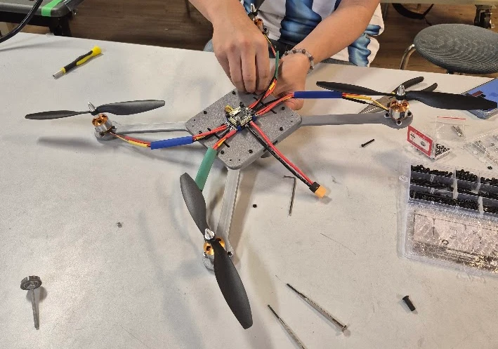
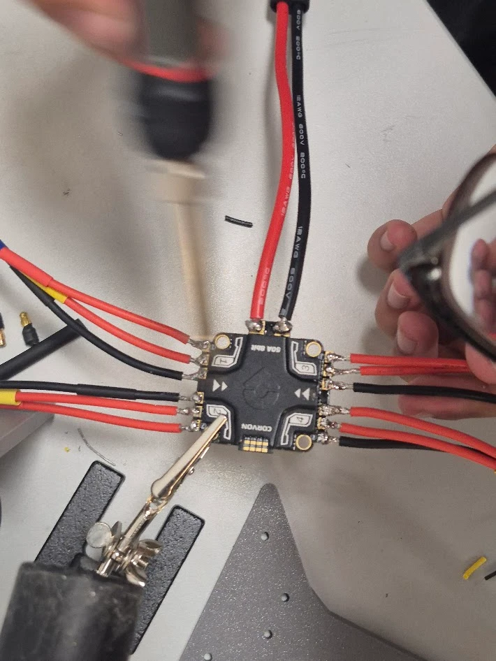
Design and CAD-model a fully custom autonomous quadcopter frame, reinforce it to survive crashes, integrate a flight-controller / ESC stack, brushless motors, and an ELRS radio system, and hand-solder every power and signal connection.

Then diagnose the flight-stability problems that showed up (frame flex, weight balance, oscillation) and fix them through redesign until the airframe hovers cleanly with a Raspberry Pi, camera, and GPS aboard.

Stack

DesignFusion 360, 3D-printed frame
Flight controllerMicoAir F405 V2 flight stack (FC + ESC)
MotorsBrushless, 1000 KV
RadioExpressLRS (ELRS)
CompanionRaspberry Pi + USB camera + GPS
AutopilotArduPilot (MAVLink / GUIDED)
VisionPython, OpenCV

The iterations

v1 → v5

01

Iteration 1

Baseline airframe

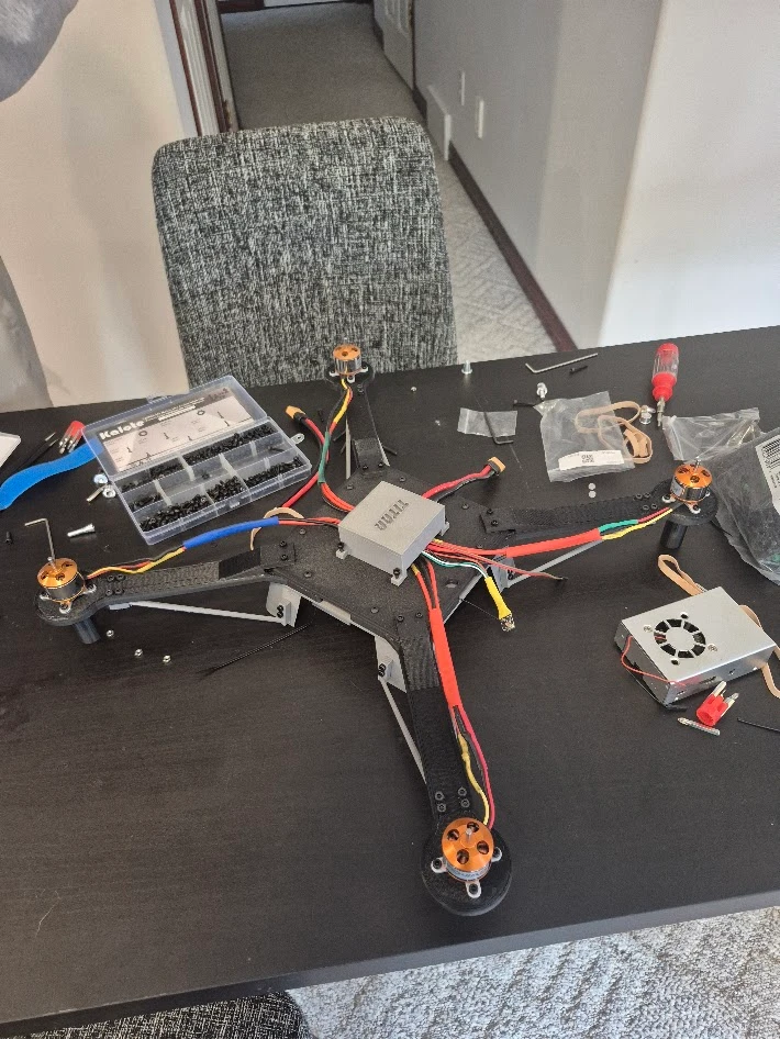
Quadcopter frame, iteration 1

First printable frame: top plate, bottom plate, and four arms. The goal was just to prove the geometry, motor mounts, and stack layout worked together.

  • Held the motors and the full flight stack solidly, and made thrust on a ground tether, a strong start
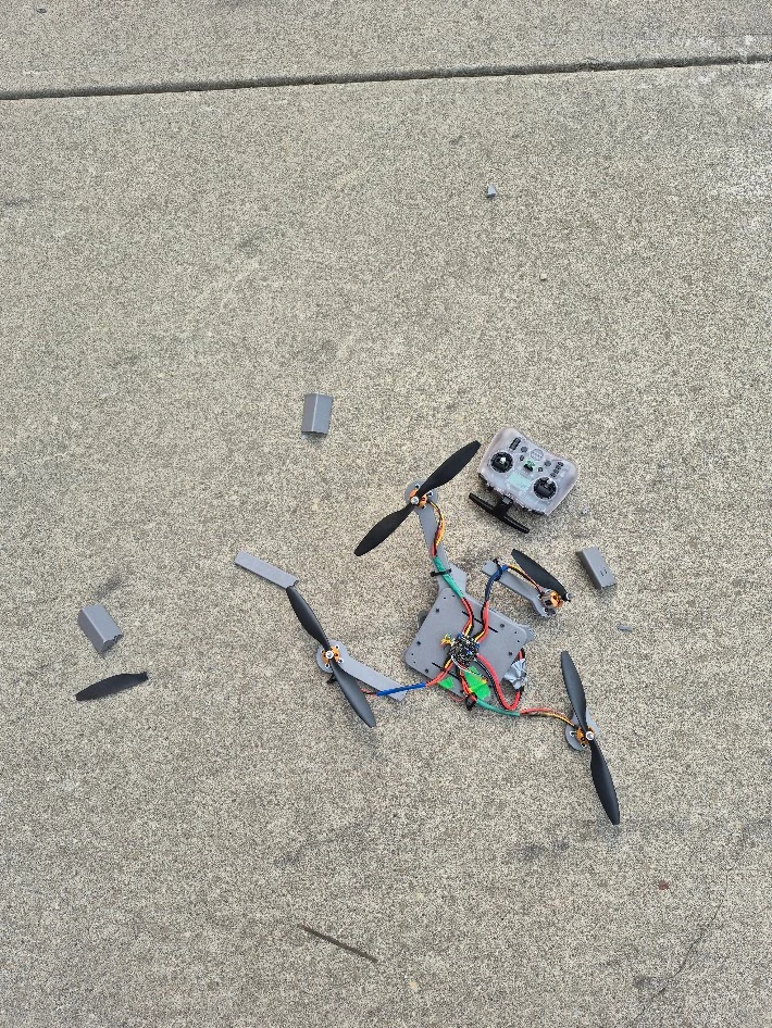
  • Arms and body were too thin: the frame snapped within five minutes of testing
  • No landing legs, so it sat flat on the floor and never got a clean lift-off
Frame size500 mm motor-to-motor
OutcomeDid not fly; frame far too flexible
02

Iteration 2

Thicker frame + landing legs

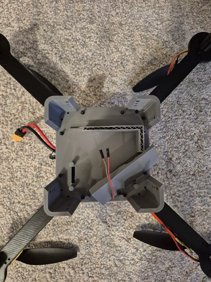
Quadcopter frame, iteration 2

Thickened the arms and the body, and added leg stilts so the battery and the Raspberry Pi could mount underneath the drone.

  • Thicker arms and body
  • New: landing legs, so the battery and Pi now mount below the frame
  • Still snapped: thick enough in CAD, but the print infill and wall pattern were too weak to back it up
Changes vs v1Arm thickness, body thickness, landing legs
OutcomeFrame broke again; did not fly at all
03

Iteration 3

Bracing, cap, first flight

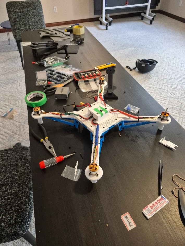
Quadcopter frame, iteration 3

Added arm stilts and a clasping arm mount to stop the arms oscillating while the propellers spun. A top cap went on to protect the flight stack in an upside-down landing, and the leg stilts were shortened, since v2 was unnecessarily tall. I also added proper Raspberry Pi and battery mounts, each placed to match the drone’s weight distribution.

  • New: arm stilts + clasping arm mount (kills arm oscillation under prop load)
  • New: arm claw (reinforces the arm-to-body joint, the exact spot that broke on v1 and v2)
  • New: top cap (protects the flight stack if it lands inverted)
  • Shorter leg stilts; dedicated Pi and battery mounts placed for balance
Problem targetedArm oscillation, joint failure, weight balance
OutcomeThe first version that flew
04

Iteration 4

Lightweighting + modular joints

Quadcopter frame, iteration 4

This iteration was about weight. Triangular cut-outs through the top body and the arms dropped the frame weight significantly. The v3 arm stilts had broken (their mounting was too thin), so I replaced some screwed joints with a friction-fit cylinder-in-hole design, which also saved weight by cutting hardware. Added a printed “Titan v4” logo on the top plate and a recessed groove to seat the radio.

  • Triangular lightening cut-outs through the top body and arms
  • Friction-fit cylinder joints replace some screws (lighter, tool-free)
  • New: recessed radio groove; printed “Titan v4” logo
  • Printed in multiple colours from separate parts
FocusWeight reduction
OutcomeFlew well until the push-pins failed; hot-glue held them together for continued testing
05

Iteration 5 · current

Final build + autonomy

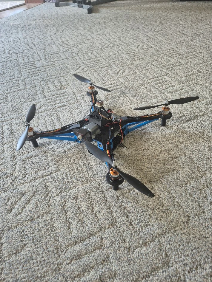
Quadcopter frame, iteration 5

The final build. I added a dedicated GPS mount and dropped v4’s friction-fit joints (the cylinders were too thin and kept snapping) and went back to screws. The print settings changed too: infill from 15% to 35% with a gyroid pattern for maximum strength. This version never broke, and it flew under the autonomous tracking code.

  • New: GPS mount
  • Friction-fit joints reverted to screws (v4’s cylinders were too thin)
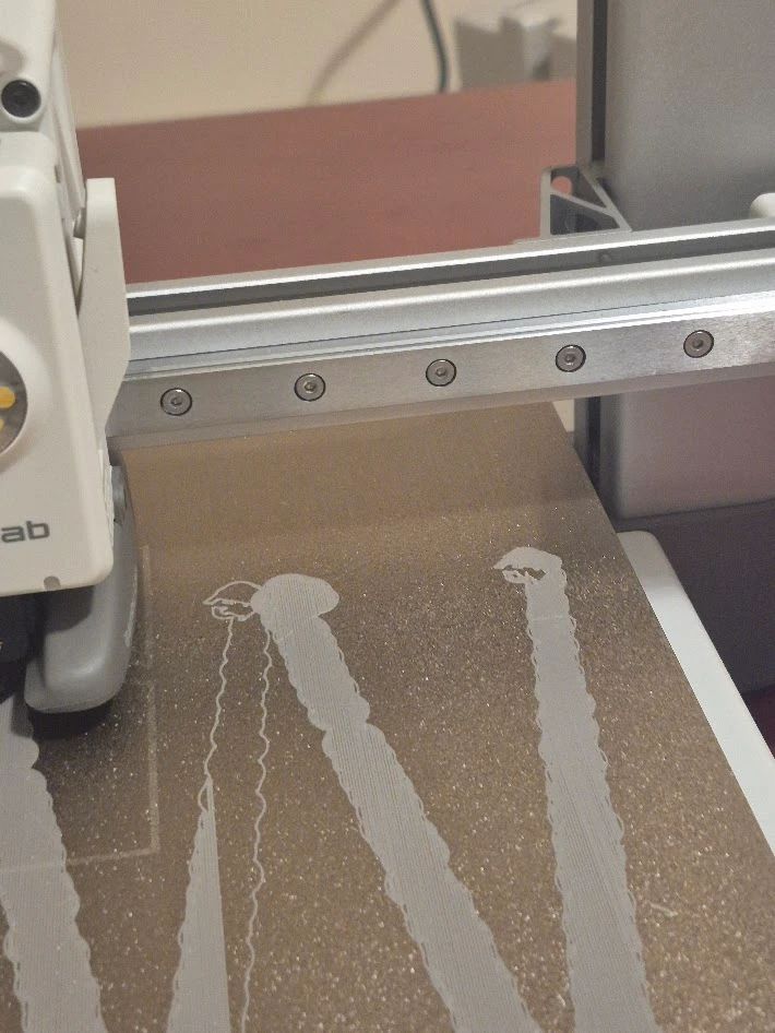
  • Print: 15% → 35% infill, gyroid pattern
  • Printed tracking target (150 mm sphere)
Print35% gyroid infill
OutcomeNever broke; flew autonomously under the tracking code

Off the screen

The build


In the air

Flight log

Autonomous: the drone is tracking the blue ball on its own (my dad is holding it).
Autonomous tracking, from further back.
← all projects